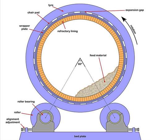
The Functional Principle of rotary kiln tyre and support roller
The purpose of kiln tyres (often called riding rings) and rollers is to support the kiln and allow it to rotate with minimal friction. Rotary kilns are among the largest items of permanently moving industrial machinery, the largest examples weighing in their fully-loaded form several thousand tonnes. Despite the challenges of their size and their high temperature, the best examples of rotary kiln rotate on their rollers almost frictionlessly, the power supplied by the drive being almost entirely in order to oppose the eccentric load of the contents of the kiln. On cutting the power to a kiln, the kiln will “roll back” and unless a brake is applied, will continue to swing like a pendulum for ten or fifteen minutes before coming to a standstill. This finely-tuned mechanical condition requires sophisticated design of the kiln’s supports.
A standardised design evolved during the first three decades of the twentieth century, allowing the great escalation in size of kilns that then followed.
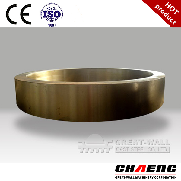
Rotary kiln tyre:
Rotary kiln tyre itself is usually a single steel casting, machined to accurately circular dimensions and with a mirror-smooth texture on all surfaces. Early tyres were occasionally produced as half-sections that could be easily assembled and replaced, but this was very soon abandoned because of the resulting rapid and erratic wear at the joints.
In the standard design, the tyre was mounted loosely on the kiln shell. Inevitably, the tyre is cooler than the kiln shell, and so a small gap allows differential expansion to take place. The gap is usually designed to be about 0.2% of shell diameter at normal operating temperature. The kiln tube bears down upon the inside of the tyre through smooth-surfaced chairs which also have lugs bracketing the tyre, preventing it from slipping along the kiln axially. The spacing of the chairs also reduces the amount of heat conduction from the kiln shell to the tyre. The tyre needs to remain relatively cool because so large a casting would be unlikely to survive a large radial temperature differential during heating up of the kiln. Another effect of the gap is that tyres would gradually precess around the kiln, with one complete turn in every 500 turns of the kiln. Measuring the rate of precession was a rough-and-ready way of assessing the width of the expansion gap while the kiln was in operation. Small changes due to wear could be adjusted by adding shims.
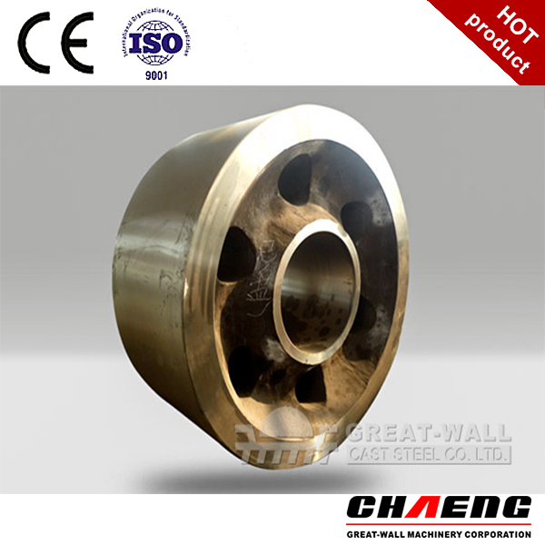
Rotary kiln support rollers:
The basic design of rollers has changed little over the years. The rollers are mounted on a massive cast iron or steel base plate which provides the inward horizontal forces on the rollers and distributes the weight of the kiln over the pier. The spacing between the rollers has to be small enough to prevent large horizontal forces, but large enough to keep the kiln laterally stable. Rollers are designed to subtend 60° at the tyre centre, and this seems always to have been the case. Minor adjustment is allowed so that the kiln can be kept aligned (i.e. to keep the centres of the tyres co-linear) as small changes take place, such as wear of the tyre or settlement of the pier.
The roller outer face is made wider than that of the tyre, mainly to allow for contraction of the kiln during shut-down. This poses a problem: if the tyre remains in one position relative to the roller, wear or plastic deformation causes a depression to form on the roller face. It is therefore normal practice to deliberately make the kiln “float” (i.e. regularly move uphill and downhill across the rollers) so that wear is evened out. Because the kiln slopes (typically 1.5° to 3.5°) it has a natural tendency to slip downhill as it turns. From the earliest times, this tendency was compensated by “cutting” the rollers – skewing their axes by a very small angle so that an uphill screw action is imparted to the tyre. This action relies upon the friction between the tyre and roller surfaces, and operators could therefore make the kiln move up or down by adjusting the amount of friction. As a further precaution to prevent the kiln from falling off its rollers, thrust rollers bearing upon the side of the tyre are used. These are usually located on the roller beds nearest the drive, where movement most needs to be restricted.
Relying upon friction, “cutting” of rollers necessarily increased the rate of wear, and after being standard practice for many years, it was abandoned from the 1950s onward in favour of the use of mechanical thrusters to float the kiln. These usually take the form of hydraulic rams attached to the thrust rollers, which are automatically controlled to impart a saw-tooth axial oscillation to the position of the kiln, with an amplitude of a few centimetres.